The construction of a country house includes many electrical works. Among them, planning and arrangement of the grounding system, which cannot be ignored for safety reasons and the requirements of the PTEC, is not the least.
Doing grounding in a private house with your own hands is not prohibited, therefore, in this material we will consider in detail the main stages of the design and installation of the circuit.
The meaning and need for grounding
The basis of the energy supply of a private house is the electric network, which is dangerous for residents, if you do not apply some measures to eliminate it. Such measures include double insulation of conductors, equalization of potentials, installation of RCDs and diflavomatov.
Grounding of the power supply network also plays an important role and is intended to divert the electric current that has appeared in the wrong place to the ground.

Technically, it looks like this: all electrical installations in the house are connected to each other and circuit breakers, and then to the ground, so that in a critical situation there was room to relieve excess voltage
One piece of reinforcement or profile clogged into the ground is not enough. Grounding is a whole system of interacting elements connected with other systems.
It cannot be mounted without picking up the parts that are suitable for the parameters and without making preliminary calculations.

To introduce the structure into the ground, you need to choose a small open plot of land near the house. It is impossible to erect a building or garage above it, since preventive or repair excavation will periodically be carried out
Between urban high-rise buildings and private housing there is a difference in the arrangement of grounding systems.
In apartment buildings, the bus is in a floor electrical panel, while for a private house, the ground loop is literally buried in the ground, since it is located nearby and does not require much effort for installation.
All requirements for the design and installation of the grounding system are set out in PTEEP 2.7.8. The owner of the house should know that the commissioning of the independently equipped structure will be carried out by the organization-supplier of electricity.
Its representatives are required to visually inspect the ground visible parts of the system once every six months, and about once every 12 years to excavate and check the condition of the underground elements.
System selection and mapping
There are three grounding systems in total: TT, IT, TN, of which the latter is divided into three more varieties - TN-S, TN-C, TN-C-S.
In private housebuilding, TN-C-S or TT system circuits are usually used, and TN-C-S looks more attractive, since there are less requirements for its installation.

Grounding system diagram TN-C-S: 1 - symbol of the ground electrode of the power source; 2 - conductive parts of the open type. At a specific point in the circuit, the ground conductor connects to the PEN
The system starts from the main grounding bus, which is installed either in the electrical panel of the house or in the cabinet of the input device.
The most rational decision is considered when the grounding is located on a support redirecting the electrical main to the house.

Electric box diagram with separated grounding and neutral conductors: 1 - electrical panel; 2 - zero conductor; 3 - grounding conductor; 4 - phase group conductors; 5 - differential current switch; 6 - automatic machines; 7 - group chains; 8 - differential automaton; 9 - electricity meter

The scheme of the TT system, which is fundamentally different in connecting the grounding conductor. It does not depend on the power source, operates offline
The TT system is used much less frequently. Representatives of the energy supplying organization are engaged in it, and if the owner nevertheless decides to save money and independently install, then the same employees of Energosnab will come to certify the documents.
If you still take a chance and choose a CT grounding scheme for a private house, then do not forget about the mandatory installation of RCDs!
Grounding Installation Instructions
There are two methods for assembling and installing underground grounding structures. The first one can be done on your own, although you will have to work hard and spend a lot of time, and the second is only for professionals, since you will need special equipment and skills to measure resistance.
Option 1 - ground wire + ground electrode
First, we will consider how to independently make grounding in a private house, without resorting to paid services. The system consists of two main elements, each of which is selected depending on the installation conditions.
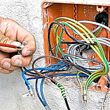
Ground wire - a copper conductor with a cross section equal to the cross section of the phase core. It is connected at one end to a bus located in the electrical panel, and at the other end to a grounding conductor buried in the ground. Grounding conductors from all electrical installations in the house also lead to the bus.

Earth wires are easily recognizable by color coding - yellow-green polymer insulation. The method of attachment to the bus is screw, by means of the installation of tips
Earthing switch - This is a structure made of steel elements that is in close contact with the ground and serves to equalize potentials when voltage appears.
When designing, take into account the parameters of soil resistance, calculate the dimensions of the rods and frames, as well as the depth.

Soil resistivity. Obviously, the value of the USG of sand, clay or peat is different. The wetter and denser the ground, the less voluminous the ground electrode system will be.
There is a universal design, for the creation of which there is no need to make complex calculations.
To make it, you will need:
- three 3-meter corners 50 * 50 mm or a steel pipe with a wall of 3 mm and a diameter of 16 mm;
- three 3-meter corners 40 * 40 mm.
You will also need a welding machine, a cutting tool, a sledgehammer, fixing materials, and for earthworks - a shovel and a bucket.
Step-by-step instruction:
- We dig a trench from the house to the installation site of the ground electrode system. Its depth and width are about half a meter.
- We make markings for driving in pins (corners) in the form of an equilateral triangle with a side of 3 m.
- In places of the vertices of the triangle we dig holes with a depth of 50 cm.
- We connect the pits with narrow grooves around the perimeter to make a triangle.
- We hammer the corners 50 * 50 into the ground so that parts of a length of about 0.2 m remain above its surface.
- We weld three corners 40 * 40 in the shape of a triangle.
- We weld a triangle to the corners hammered into the ground.
Then we connect the grounding conductor to the structure: we press in its end with a round tip and, using a suitable size bolt, fasten it to the hole drilled in one of the corners.

Grounding installation diagram. The conductor leads from the buried triangular structure to the house and ends in an electrical panel on the grounding bus
Metal parts must be covered with soil, preferably sand, and the place of installation of the ground electrode and conductor should be marked with a sign so that it does not damage during construction or economic work.
Recommendations for the selection of parts and installation of the ground electrode system in the ground:
Image Gallery
Photo from
Factory products have advantages over do-it-yourself products: they are delivered complete, do not require welding, allow you to get the necessary resistance with a minimum of earthwork
To hammer long 3-meter corners into the ground, at the first stage you will need a stepladder or other elevation from which you can strike with a power tool or a sledgehammer
To preserve the conductivity of the metal corner as much as possible, the structural elements do not need to be coated with protective anticorrosion paint or other similar composition
In addition to the steel angle of 50 * 50 cm, you can use a 6 mm galvanized rod, a 10 mm ferrous metal rod or rectangular steel 48 mm²
The best option for the grounding bus is an electrotechnical bronze plate with holes for connecting the grounding conductors. It is mounted on the wall of the electric box
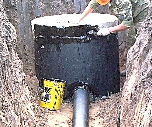
The grounding structure is recommended to be buried in the ground as close to the foundation of the house as possible - at a distance of about 1 m
To make homemade metal elements more easily clogged into the ground, the ends of the corners must be sharpened by cutting with a saw. Factory products are equipped with a pointed head
So that the joints do not oxidize and increase the resistance of the ground electrode, welding is used instead of screws, which guarantees a strong and long seam
Factory earthing equipment
Step-ladder or specially knitted stand
Galvanized Steel Corner
Metal rolling for the manufacture of an earthing switch
Earth bar in the electrical panel
Ground loop near the house
Grounding installation
Welding ferrous metal parts
Edible salt is dangerous for steel rods and the strip connecting them - it corrodes the metal and renders the structure unusable. Make sure that this substance does not accidentally get into the ground near the ground electrode system.
Option 2 - Modular Pin System
If the construction of metal parts can be done by yourself, then the factory pin must be purchased at the store.
Its main advantage is the absence of labor-intensive excavation and welding, and the disadvantage is the additional cost of paying for the services of a service organization.

The mounting scheme of the pin earthing switch and its device. The main components are the head, a steel electrode with an electrochemical copper coating, and couplings connecting the fragments of the electrode

The great depth is also explained by the fact that groundwater is usually present in the indicated range, which sharply reduces the resistance of the device, and this is a necessary condition for creating a grounding system
In a home-made design, the area of contact with the soil increases due to the use of several corners. There is only one pin, so the increase in contact occurs due to its length. The device is driven into the ground to a depth of 20-40 m.
Earthwork is reduced to pulling out one hole with dimensions of 0.5 * 0.5 * 0.4 m. It is not recommended to use a hammer drill to hammer a pin, since rotation of the pin head should be excluded. Here you need a hammer drill with a special nozzle.
In the factory kit, together with the pin, there is a clip for attaching the ground conductor, so the installation process consists in driving the main device and connecting it to the wire.

Step-by-step installation instructions for a pin earthing switch. Only a specialist, a representative from a service organization, can measure spreading with a multimeter and calculate the installation depth.
There are standards that should be followed during installation:
- for 3-phase 380 V - resistance no more than 2 Ohms;
- for 1-phase 220 V network - resistance no more than 4 Ohms.
With self-assembly for safety in front of the inspection bodies, it is better to accurately calculate the level of groundwater and make sure that the ground electrode drops to this level.
Upon contact with groundwater, the resistance parameters will return to normal.
DIY grounding device experience:
Practical tips for installing a factory made earthing switch:
Installation of an earthing system of several rods:
As you can see, you can install the grounding system yourself, so using a team of invited electricians - the first way is cheaper, but more complicated, the second is expensive, but reliable.
However, the main thing in competent installation is the result that should make the power grid of the house completely safe for its owners.
Do you have any questions about the hand-made arrangement of the ground loop? Ask them below under the article - our experts and competent site visitors will try to help you.
If you notice inaccuracies or errors in the above material, or want to add useful information to the article, please write to us in the comments section.