Any owner of a private house seeks to minimize the cost of heating the home. In this regard, heat pumps are much more profitable than other heating options; they give 2.5-4.5 kW of heat from one kilowatt of electricity consumed. The reverse side of the coin: to get cheap energy, you will have to invest a lot of money in equipment, the most modest heating installation with a capacity of 10 kW will cost 3500 y. e. (starting price).
The only way to reduce costs by 2-3 times is to make a heat pump with your own hands (abbreviated as TN). Consider a few real working options, assembled and tested by master enthusiasts in practice. Since the manufacture of a complex unit requires basic knowledge about refrigeration machines, let's start with the theory.
Features and operating principle of VT
How is the heat pump different from other installations for heating private houses:
- unlike boilers and heaters, the unit itself does not produce heat, but, like an air conditioner, moves it inside the building;
- The VT was named the pump because it “pumps out” energy from sources of low-grade heat — ambient air, water, or soil;
- the unit is powered exclusively by electricity consumed by the compressor, fans, circulation pumps and control board;
- the unit’s operation is based on the Carnot cycle used in all refrigeration machines, for example, air conditioners and split systems.

Reference. Heat is contained in any substance whose temperature is above absolute zero (minus 273 degrees). Modern technologies allow you to take the specified energy from the air with temperatures up to -30 ° C, earth and water - up to +2 ° C.
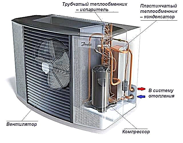
In the Carnot heat exchange cycle, a working fluid is involved - gas freon, boiling at minus temperature. By alternately evaporating and condensing in two heat exchangers, the refrigerant absorbs environmental energy and transfers it into the building. In general, the principle of the heat pump repeats the operation of the air conditioner, included in the heating:
- Being in the liquid phase, freon moves through the tubes of an external heat exchanger-evaporator, as shown in the diagram. Receiving heat of air or water through metal walls, the refrigerant heats up, boils and evaporates.
- Then the gas enters the compressor, forcing pressure to the calculated value. Its task is to raise the boiling point of the substance so that freon condenses at a higher temperature.
- Passing through an internal heat exchanger-condenser, the gas again turns into a liquid and gives up the accumulated energy to the heat carrier (water) or to the room air directly.
- At the last stage, the liquid refrigerant enters the receiver – moisture separator, then into the throttling device. The pressure of the substance drops again, freon is ready to go through a second cycle.

Note. Conventional split systems and factory heat pumps have a common feature - the ability to transfer energy in both directions and operate in 2 modes - heating / cooling. Switching is implemented using a four-way reversing valve that changes the direction of gas flow along the circuit.
In household air conditioners and VTs, various types of thermostatic valves are used, which reduce the pressure of the refrigerant in front of the evaporator. In household split systems, the role of the regulator is played by a simple capillary device, an expensive thermostatic valve (TRV) is installed in the pumps.
Note that the above cycle occurs in all types of heat pumps. The difference lies in the methods of supply / removal of heat, which we list below.

Varieties of installations
According to the generally accepted classification, VTs are divided into types according to the source of energy received and the type of coolant to which it is transferred:
- Air-to-air pumps are the closest to traditional split systems, the difference is in the area of the external evaporator. The device takes away the heat of the environment and directly transfers the air to the room, as happens in a conventional air conditioner.
- The design of the air-water generators is identical, but provides for the heating of water or antifreeze circulating through the heating system of a residential building.
- The installation of the type "water-water" takes the low-grade heat of the reservoir and transfers it to the liquid coolant. An additional external pipe heat exchanger is used here, immersed in a well, a lake, a well, or a septic tank. The circulation of water through the evaporator provides a second pump.
- Geothermal heat pump uses the heat of the soil and heats the internal house coolant. The external heat exchange circuit is a coil with antifreeze, deepened by 1.5–2 m and occupying a large area. The second option is several vertical probes from pipes lowered into the wells to a depth of 10-100 meters.

Reference. Varieties of heat pumps are listed in order of increasing cost of equipment along with installation. Aerial installations are the cheapest; geothermal installations are expensive.
The main parameter characterizing a heat pump for heating a house is the COP efficiency coefficient, which is equal to the ratio between the energy received and consumed. For example, relatively inexpensive air heaters cannot boast a high COP - 2.5 ... 3.5. We explain: having spent 1 kW of electricity, the installation supplies 2.5–3.5 kW of heat to the dwelling.

Water and ground systems are more efficient, their real coefficient lies in the range of 3 ... 4.5. Productivity - a variable value, depending on many factors: the design of the heat exchange circuit, immersion depth, temperature and water flow.
An important point. Hot-water heat pumps are not able to heat up the coolant to 60–90 ° С without additional circuits. The normal temperature of the water from the transformer is 35 ... 40 degrees, the boilers here clearly win. Hence the manufacturer's recommendation: connect the equipment to low-temperature heating - water heated floors.
Which VT is better to collect
We state the problem: we need to build a home-made heat pump at the lowest cost. A number of logical conclusions follow from this:
- The installation will have to use a minimum of expensive parts, so it will not be possible to achieve a high COP value. In terms of performance, our device will lose to factory models.
- Accordingly, it makes no sense to make a purely air VT, it is easier to use an inverter air conditioner in heating mode.
- To get real benefits, you need to make a heat pump "air - water", "water-water" or build a geothermal installation. In the first case, it is possible to achieve a COP of about 2–2.2, in the remaining cases, an indicator of 3–3.5 can be achieved.
- It is not possible to do without underfloor heating circuits. A heat carrier heated to 30-35 degrees is incompatible with the radiator network, except in the southern regions.

Comment. Manufacturers claim: the inverter split system operates at a street temperature of minus 15-30 ° C. In fact, the heating efficiency is significantly reduced. According to homeowners, on frosty days, the indoor unit delivers a faintly warm air stream.
For the implementation of the water version of VT certain conditions are required (to choose):
- a pond 25-50 m from the home, at a greater distance, electricity consumption will increase significantly due to the powerful circulation pump;
- a well or a well with a sufficient supply (debit) of water and a place for discharge (pit, second well, gutter, sewage);
- prefabricated sewer collector (if you are allowed to crash there).
Groundwater consumption is easy to calculate.In the process of heat selection, a home-made heat pump will lower their temperature by 4-5 ° С, from here the flow volume is determined through the heat capacity of water. To get 1 kW of heat (we take 5 degrees delta of water temperatures), about 170 liters must be driven through the VT for an hour.
Heating a house with an area of 100 m² will require a power of 10 kW and a water consumption of 1.7 tons per hour - the volume is impressive. Such a thermal water pump will fit for a small country house of 30-40 m², preferably insulated.

The assembly of the geothermal system is more real, although the process is rather laborious. The option of horizontal layout of the pipe over an area at a depth of 1.5 m is immediately dismissed - you have to shovel the entire section or pay money for the services of earthmoving equipment. The method of punching wells is much easier and cheaper to implement, practically without disturbing the landscape.
The simplest heat pump from a window air conditioner
As you might guess, for the manufacture of water-to-air pumps, a window cooler in working condition is required. It is very advisable to buy a model equipped with a reversing valve and capable of working for heating, otherwise you will have to redo the freon circuit.
Tip. When buying a used air conditioner, pay attention to the nameplate, which displays the technical characteristics of the household appliance. The parameter you are interested in is the device's cold performance (indicated in kilowatts or British thermal units - BTU).

With some luck, you don’t even have to let out freon and solder tubes. How to convert air conditioning into a heat pump:
- Remove the upper casing of the unit and unscrew the external heat exchanger from the pallet. Carefully move the radiator, taking care not to bend the refrigerant pipes.
- Remove the outer impeller from the common shaft.
- Make a metal tank along the length of the external heat exchanger, make the width 10-15 cm larger. Cut the fittings for the supply of running water into the side walls.
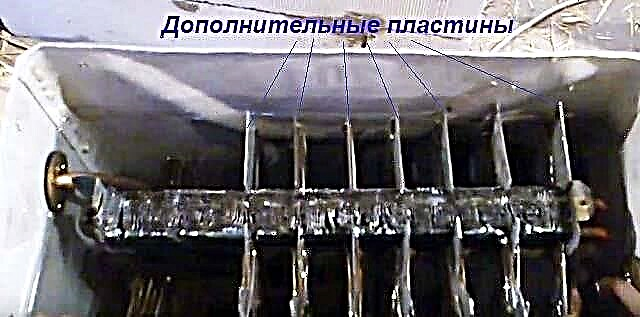
- To prevent the radiator from freezing, increase the exchange area by adding copper or aluminum plates on the sides (depending on the material of the heat exchanger).
- Immerse the radiator in the tank, preferably without cutting the freon tubes. Seal the cap and seal the contour entries.
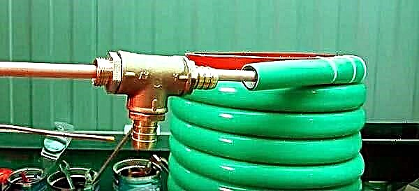
- Connect the water inlet and outlet hoses to the fittings, connect the circulation pumps. Fill and check tank for leaks.

Recommendation. If the heat exchanger cannot be placed in the tank without disturbing the freon lines, try to evacuate the gas and cut the pipes at the desired points (away from the evaporator). After assembling the water heat exchange unit, the circuit will have to be soldered and filled with freon. The amount of refrigerant is also indicated on the plate.
Now it remains to launch a home-made VT and adjust the water flow, achieving maximum efficiency. Please note: an impromptu heater uses a completely factory "filling", you just moved the radiator from air to liquid. How the system works live, look at the video of the master craftsman:
Making a geothermal installation
If the previous option will allow you to achieve approximately double savings, then even a homemade ground loop will give COP in the region of 3 (three kilowatts of heat per 1 kW of consumed electricity). True, financial and labor costs will also increase significantly.
Although a lot of examples of assembling such devices are published on the Internet, a universal instruction with drawings does not exist. We will offer a working version, assembled and tested by a real home master, although many things will have to be thought out and completed independently - all the information about heat pumps is difficult to put in one publication.
Calculation of soil circuit and pump heat exchangers
Following our own recommendations, we proceed to the calculations of a geothermal pump with vertical U-shaped probes placed in wells.It is necessary to find out the total length of the external contour, and then the depth and number of vertical shafts.
Initial data for an example: you need to heat a private insulated house with an area of 80 m² and a ceiling height of 2.8 m, located in the middle lane. We will not calculate the load on heating; we will determine the need for heat by area, taking into account thermal insulation - 7 kW.

Important clarification. Engineering calculations of heat pumps are quite complex and require highly skilled performer, whole books are devoted to this topic. The article provides simplified calculations taken from the practical experience of builders and craftsmen who love homemade products.
The intensity of heat exchange between the ground and the non-freezing fluid circulating along the contour depends on the type of soil:
- 1 linear meter of a vertical probe immersed in groundwater will receive about 80 watts of heat;
- in rocky soils, heat removal will be about 70 W / m;
- clay soils saturated with moisture will give out about 50 W per 1 m of collector;
- dry breeds - 20 W / m.
Reference. The vertical probe consists of 2 loops of pipes lowered to the bottom of the well and filled with concrete.
An example of calculating the length of a pipe. To extract the necessary 7 kW of heat energy from raw clay, you need to divide 7000 W by 50 W / m, we get the total depth of the probe 140 m. Now the pipeline is distributed over the wells with a depth of 20 m, which you can drill with your own hands. A total of 7 drillings of 2 heat transfer loops, the total length of the pipe is 7 x 20 x 4 = 560 m.

The next step is to calculate the heat transfer area of the evaporator and condenser. Various calculation resources are offered on various Internet resources and forums, in most cases incorrect. We will not take the liberty of recommending such techniques and misleading you, but we will offer some tricky option:
- Contact any well-known manufacturer of plate heat exchangers, for example, Alfa Laval, Kaori, Anvitek and so on. You can go to the official website of the brand.
- Fill out the selection form for the heat exchanger or call the manager and order the selection of the unit, listing the parameters of the media (antifreeze, freon) - temperature at the inlet and outlet, heat load.
- A specialist of the company will make the necessary calculations and propose a suitable heat exchanger model. Among its characteristics you will find the main one - the surface area of the exchange.
Lamellar aggregates are very effective, but expensive (200-500 euros). It is cheaper to assemble a shell-and-tube heat exchanger from a copper tube with an outer diameter of 9.5 or 12.7 mm. Multiply the figure given by the manufacturer by a safety factor of 1.1 and divide by the circumference of the pipe to get the footage.

Example. The heat exchange area of the proposed unit was 0.9 m². Choosing a ½ ”copper tube with a diameter of 12.7 mm, we calculate the circumference in meters: 12.7 x 3.14 / 1000 ≈ 0.04 m. We determine the total footage: 0.9 x 1.1 / 0.04 ≈ 25 m.
Equipment and materials
It is proposed that the future heat pump be built on the basis of the outdoor unit of a split system of suitable power (indicated on the plate). Why is it better to use a used air conditioner:
- the device is already equipped with all components - a compressor, a choke, a receiver and starting electrics;
- home-made heat exchangers can be placed in the body of the refrigeration machine;
- There are convenient service ports for refueling freon.
Note. Understanding the topic, users select equipment separately - compressor, expansion valve, controller, and so on. With experience and knowledge, this approach is only welcome.
It is not practical to assemble VT on the basis of an old refrigerator - the capacity of the unit is too small. In the best case, it will be possible to “squeeze” up to 1 kW of heat, which is enough to heat one small room.

In addition to the external split unit, the following materials will be needed:
- PND pipe Ø20 mm - on the ground loop;
- polyethylene fittings for assembling collectors and connecting to heat exchangers;
- circulation pumps - 2 pcs.;
- manometers, thermometers;
- high-quality water hose or HDPE pipe with a diameter of 25–32 mm to the shell of the evaporator and condenser;
- copper tube Ø9.5-12.7 mm with a wall thickness of at least 1 mm;
- insulation for pipelines and freon highways;
- a set for sealing heating cables laid inside the water supply (needed to seal the ends of copper pipes).

As an external coolant, a saline solution of water or antifreeze for heating - ethylene glycol is used. You will also need a stock of freon, whose brand is indicated on the nameplate of the split system.
Heat Exchanger Assembly
Before starting installation work, the outdoor module must be disassembled - remove all covers, remove the fan and a large regular radiator. Disconnect the solenoid that controls the reversing valve if you do not plan to use the pump as a cooler. Temperature and pressure sensors must be maintained.
Assembly order of the main unit VT:
- Fabricate the condenser and evaporator by inserting the copper tube into the hose of the calculated length. At the ends, install tees for connecting the soil and heating circuit, seal the protruding copper pipes with a special kit for the heating cable.
- Using a piece of plastic pipe Ø150-250 mm as a core, wrap home-made two-pipe circuits and output the ends in the right directions, as is done below in the video.
- Place and fix both shell-and-tube heat exchangers in place of the standard radiator, solder the copper pipes to the corresponding terminals. It is better to connect a “hot” heat exchanger – condenser to the service ports.
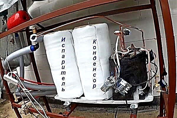
- Install factory sensors that measure refrigerant temperature. Insulate bare sections of tubes and the heat exchangers themselves.
- On the water lines, put thermometers and manometers.


Tip. If you plan to put the main unit on the street, you need to take measures against the solidification of the oil in the compressor. Purchase and install a winter oil sump electric heating kit.
At the thematic forums, another method of manufacturing an evaporator is found - a copper tube is wound in a spiral, then inserted into a closed container (tank or barrel). The option is quite reasonable with a large number of turns, when the calculated heat exchanger simply does not fit in the air conditioner case.
Ground contour device
At this stage, simple but labor-intensive excavation work and laying out the probes in the wells are performed. The latter can be done manually or invite the drilling machine. The distance between adjacent wells is at least 5 m. The further work procedure:
- Dig a shallow trench between the holes to lay the supply pipes.
- In each hole, lower 2 loops of polyethylene pipes and fill the pits with concrete.
- Bring the lines to the connection point and mount the common collector using HDPE fittings.
- Insulate the pipelines laid in the ground and fill it with soil.

An important point. Before concreting and backfilling, be sure to check the tightness of the circuit. For example, connect an air compressor to the manifold, inflate 3-4 bar and leave for several hours.
When connecting the highways, follow the diagram below. Bends with taps will be needed when filling the system with brine or ethylene glycol. Lead two main pipes from the collector to the heat pump and connect to the “cold” heat exchanger – evaporator.

Similarly, the condenser is connected to the home system of underfloor heating. A mixing unit with a three-way valve is optionally mounted due to the low flow temperature.If it is necessary to combine VTs with other heat sources (solar collectors, boilers), use a buffer tank for several conclusions.
Refueling and starting the system
After installing and connecting the unit to the mains, an important stage begins - filling the system with refrigerant. A pitfall awaits here: you don’t know how much freon needs to be refilled, because the volume of the main circuit has grown significantly due to the installation of a makeshift condenser with an evaporator.
The issue is solved by refueling by pressure and superheat temperature of the freon, measured at the compressor inlet (there freon is supplied in a gaseous state). Detailed instructions for filling with the temperature measurement method are outlined in the following manual.
The second part of the video shows how to fill the system with R22 freon in terms of pressure and temperature of the refrigerant overheating:
After refueling, turn on both circulation pumps at the first speed and start the compressor in operation. Indicate the temperature of the brine and the internal coolant by thermometers. At the stage of heating, the lines with the refrigerant can freeze, subsequently the frost should melt.
Conclusion
It is very difficult to make and start a thermal geothermal pump with your own hands. Surely, repeated improvements, bug fixes, and settings will be required. As a rule, most of the problems in self-made VTs arise due to improper assembly or refueling of the main heat exchange circuit. If the unit immediately fails (safety automation has worked) or the heat carrier does not heat up, it is worth calling the refrigeration equipment wizard - it will carry out diagnostics and indicate the mistakes made.